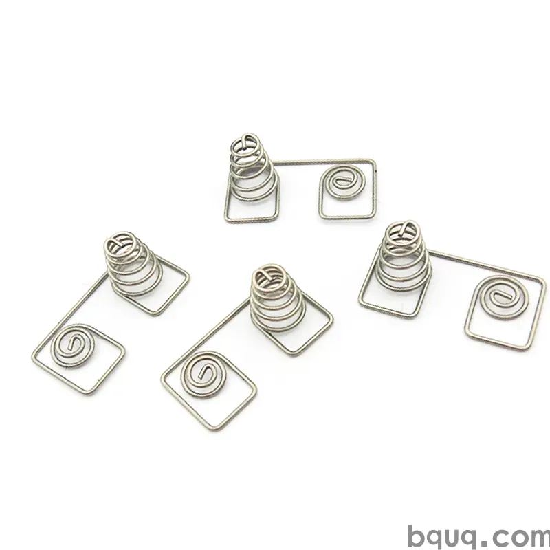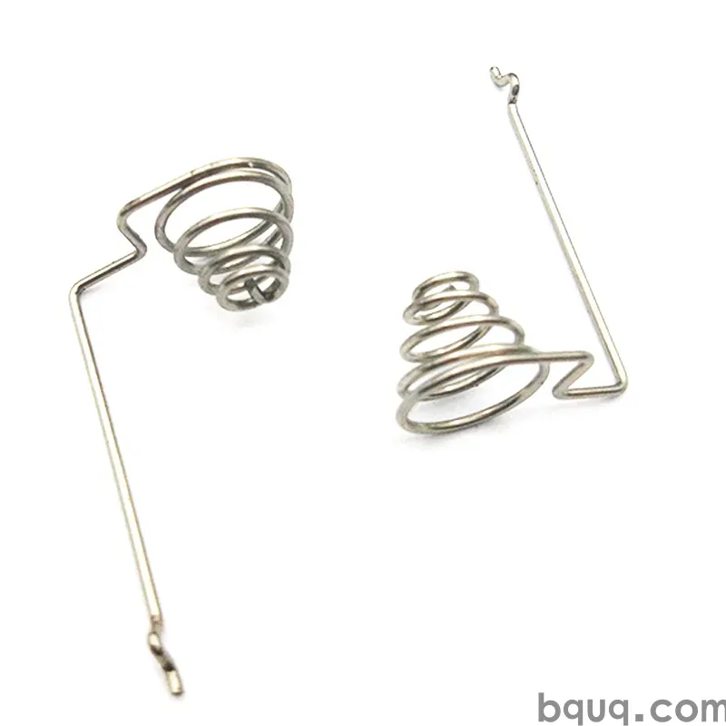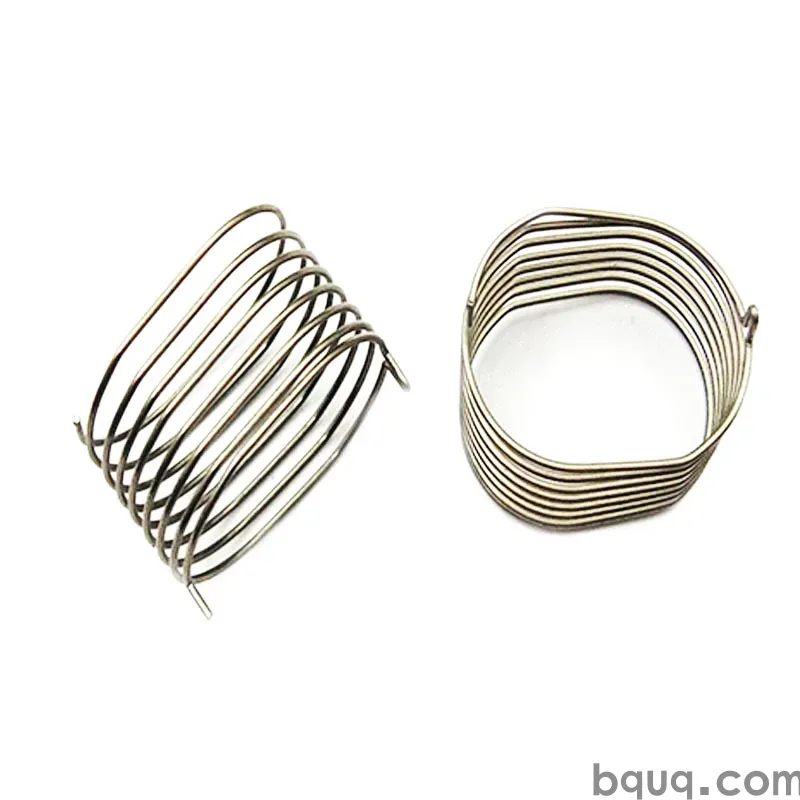
Progettazione schermatura EMI: contatti a molla stampati, finger stock e cans che superano i test sulle emissioni irradiate — da una fabbrica ISO9001 di Dongguan.
Schermatura EMI: Progettazione di Contatti a Molla e Cans che Superano i Test
Risposta breve: la schermatura EMI fallisce negli spazi vuoti, non attraverso il metallo. Un contenitore schermato stampato o un contatto a molla è valido solo quanto i giunti tra i suoi pannelli — le giunzioni dove i coperchi incontrano i telai, e le dita che li collegano. Progettate quelle interfacce con un numero sufficiente di punti di contatto, forza di contatto e placcatura, e un contenitore stampato supera i test sulle emissioni irradiate; lasciate uno spazio di 1 mm o una molla che si rilassa e nessuna quantità di metallo di schermatura salverà il risultato.
Ogni prodotto elettronico con un limite di emissioni irradiate — che in pratica significa tutto ciò che viene venduto commercialmente — si affida a parti metalliche stampate per mantenere il rumore dentro e le interferenze fuori. Il contenitore di schermatura che copre un modulo, le dita a molla che mettono a terra un coperchio rimovibile e la clip che collega una scheda al suo telaio sono tutti stampati. La loro geometria è semplice; il loro compito è spietato. Questa guida copre le regole di progettazione che fanno sì che la schermatura stampata superi il test al primo colpo.
Perché la Schermatura Fallisce nelle Giunzioni
Una scatola metallica solida è uno schermo perfetto — il problema è che nessun prodotto reale è una scatola solida. I coperchi devono aprirsi, le schede devono scorrere dentro, i cavi devono passare attraverso. Ogni apertura è un'antenna a fessura che perde a lunghezze d'onda correlate alla sua lunghezza. Uno spazio di pochi centimetri può perdere alle frequenze dei telefoni cellulari; anche una giunzione sottilissima perde dove le due superfici non si toccano effettivamente metallo su metallo.
| Tipo di spazio/giunzione | Problema tipico di perdita | Soluzione di schermatura |
|---|---|---|
| Giunzione coperchio-telaio | Antenna a fessura lunga | Dita a molla ogni pochi cm |
| Contatto scheda-schermo | Messa a terra intermittente | Clip stampate, bordi messi a terra |
| Ritagli per connettori | Perdita da apertura | Guarnizioni, estensioni del contenitore, spaziatura delle viti |
| Fori di ventilazione | Aperture grandi | Schema di perforazione sotto λ/20 |
| Solo punti di vite | Spazi tra gli elementi di fissaggio | Aggiungere dita o guarnizione conduttiva |
Concetto chiave: l'efficacia della schermatura è decisa dallo spazio peggiore, non dal pannello medio. I progettisti che calcolano la schermatura sul metallo e ignorano le giunzioni ricevono una sorpresa sgradevole al laboratorio di conformità, motivo per cui i contatti a molla e la geometria del contenitore meritano tanta attenzione quanto il materiale dell'involucro.
Contenitori di Schermatura Stampati: La Struttura di Base
Il contenitore di schermatura stesso è una scatola stampata in lamiera — tipicamente acciaio placcato stagno, argento nickel o alluminio — che si posiziona sopra un circuito rumoroso e viene saldato o agganciato alla massa della scheda. Lo stampaggio rende i contenitori economici in grandi volumi, con pareti imbutite, linguette di bloccaggio e caratteristiche di montaggio sulla scheda formate in un unico stampo. L'efficacia di schermatura del contenitore dipende dal suo materiale, dalle sue giunzioni e da quanto completamente si collega al piano di massa.
| Materiale del contenitore | Uso tipico | Note |
|---|---|---|
| Acciaio placcato stagno | Contenitori per uso generale | Buona SE, saldabile, basso costo |
| Argento nickel | Aree sensibili alla corrosione | Buona saldabilità, finitura più bianca |
| Alluminio | Moduli sensibili al peso | Richiede percorso di messa a terra separato |
| Lega di rame | Moduli RF | Migliore conduttività, più costoso |
Concetto chiave: il materiale conta meno della continuità. Un contenitore in acciaio con dita ogni 10 mm supera un contenitore in rame messo a terra con una sola vite, perché le dita chiudono le giunzioni che effettivamente perdono. I nostri involucri stampati in lamiera sono progettati con questa logica di giunzione al primo posto, spessore della parete e materiale al secondo.
Contatti a Molla: I Chiusori di Spazi
I contatti a molla e il finger stock esistono per premere due superfici metalliche insieme in modo affidabile, per migliaia di cicli di apertura e chiusura, senza saldatura. Devono fornire tre cose contemporaneamente: forza di contatto sufficiente per mantenere bassa la resistenza, deflessione sufficiente per tollerare l'accumulo di tolleranze e l'usura, e un materiale che non si rilassi nel corso della vita. Ecco perché il berillio-rame domina la categoria, con bronzo fosforoso e acciaio inossidabile indurito come alternative guidate dal costo.
| Materiale | Temperatura massima di servizio tipica | Fatica/rilassamento | Uso tipico |
|---|---|---|---|
| Berillio-rame C172 | ~150 °C+ | Eccellente | Schermi a livello di scheda, dita |
| Bronzo fosforoso C5210 | ~100–150 °C | Buono | Dita e clip a costo inferiore |
| Acciaio inossidabile 301 indurito | ~250 °C+ | Buono | Alte temperature e ambienti difficili |
| Ottone, argento nickel | ~100 °C | Discreto | Solo clip di messa a terra statiche |
Concetto chiave: scegliere il materiale della molla in base alla temperatura e alla durata del ciclo, quindi placcarlo per l'ambiente di corrosione e usura. Una molla che si rilassa è un guasto silenzioso — lo schermo funziona bene al primo articolo e perde un anno dopo, motivo per cui la resistenza al rilassamento conta più della conduttività grezza nei contatti a molla stampati.
I Numeri di Progettazione che Contano
Tre numeri determinano se un contatto a molla supera il test: forza di contatto, intervallo di deflessione e placcatura all'interfaccia. La forza deve rimanere abbastanza alta da superare le pellicole superficiali — ossidi e contaminazione — tipicamente decine di grammi per dita come minimo, scalati in base al dovere. La deflessione deve coprire l'accumulo di tolleranze tra il coperchio e il telaio senza sovraccaricare il materiale. La placcatura, solitamente stagno o oro su nichel, mantiene la superficie di accoppiamento conduttiva nel tempo.
| Parametro di progettazione | Valore/regola tipica | Modalità di guasto se sbagliato |
|---|---|---|
| Forza di contatto per dita | 30–150 gf tipico | Forza bassa = resistenza della pellicola di ossido |
| Deflessione di lavoro | 20–50% dell'altezza libera | Deflessione eccessiva = deformazione permanente |
| Passo delle dita | 5–15 mm tipico | Passo più ampio = perdite dalla giunzione |
| Placcatura | Stagno o flash d'oro su nichel | Metallo nudo si corrode nella zona di contatto |
| Superficie di accoppiamento | Pulita, piatta, placcata | Vernice o anodizzazione uccide il giunto |
Concetto chiave: questi numeri interagiscono. Aumentate la forza e avrete bisogno di materiale più rigido o più spazio di deflessione; aumentate la deflessione e avrete bisogno di una migliore durata a fatica. Il disegno dovrebbe indicare la forza a una data deflessione, non solo un'altezza libera — questa singola specifica è ciò che rende un contatto a molla prevedibile sulla linea di assemblaggio e in laboratorio.
Placcatura e Messa a Terra: La Metà Elettrica
Una molla che tocca una superficie anodizzata o verniciata non sta mettendo a terra nulla. La superficie di accoppiamento sul coperchio o sul telaio deve essere metallo nudo e placcato, e la molla stessa necessita di una placcatura adatta all'ambiente — stagno per il costo, flash d'oro dove il prodotto vede atmosfere corrosive o livelli di segnale molto bassi. Anche la strategia di messa a terra conta: le dita mettono a terra il coperchio al telaio, le clip mettono a terra la scheda al telaio, ed entrambi i percorsi devono arrivare allo stesso riferimento di massa a cui si collega il contenitore di schermatura.
| Interfaccia | Coppia di placcatura | Motivo |
|---|---|---|
| Dita a superficie del coperchio | Stagno-stagno o Au-stagno | Resistenza di contatto bassa e stabile |
| Contenitore a pad della scheda | Giunto di saldatura | Legame permanente e ad alta integrità |
| Clip a telaio | Stagno o nichel | Giunto a pressione resistente alla corrosione |
| Bordo scheda a contenitore | Multiple clip in parallelo | Ridondanza per la messa a terra |
Concetto chiave: trattate ogni interfaccia come un giunto elettrico con una specifica di placcatura, non come metallo che tocca metallo. La stessa logica di placcatura che protegge i contatti elettrici stampati si applica alla schermatura, e gli stessi registri di ispezione dovrebbero seguire le parti nella produzione.
Superare il Test al Primo Colpo
I test di conformità sono costosi, quindi progettate margini di schermatura prima della visita in laboratorio. Posizionate le dita più vicine di quanto richiesto dal calcolo per coprire usura e tolleranze, specificate lo spessore della placcatura con margine e prototipate l'assemblaggio effettivo di coperchio e telaio — un contenitore di schermatura testato da solo non dice nulla sulla giunzione tra esso e il coperchio. Le costruzioni campione che includono le dita stampate, il contenitore e la superficie di accoppiamento troveranno problemi di messa a terra mentre sono ancora modifiche CAD, non riprogettazioni.
Sul lato produzione, la coerenza è la variabile che fa superare il test: le dita stampate da un lotto di bobina si comportano come quelle del lotto successivo solo se la tempra del materiale e la placcatura rimangono in specifica. Ecco perché eseguiamo parti di schermatura stampate con ispezione della bobina in ingresso e registri di placcatura per lotto sotto ISO9001 — uno schermo che varia da lotto a lotto è un risultato di test che varia da lotto a lotto.
Domande Frequenti
D: Quante dita a molla servono per un coperchio di schermatura?
Abbastanza perché la spaziatura tra i punti di contatto rimanga sotto la lunghezza d'onda della frequenza più alta che dovete contenere — in pratica, dita ogni 5–15 mm attorno al perimetro del coperchio. Meno dita significano fessure più lunghe e più perdite alle alte frequenze.
D: Berillio-rame o bronzo fosforoso per le dita EMI?
Il berillio-rame vince sulla resistenza al rilassamento e sulla durata del ciclo, motivo per cui domina la schermatura a livello di scheda. Il bronzo fosforoso è accettabile per design a ciclo inferiore e sensibili al costo. Se l'ambiente è caldo, l'acciaio inossidabile indurito è la scelta durevole.
D: Il contenitore di schermatura deve essere saldato tutto attorno?
No — i contenitori sono spesso agganciati o saldati a punti in pochi punti. Ciò che conta è che il contenitore si colleghi al piano di massa in più punti e che qualsiasi apertura rimanga piccola. La saldatura a tutto perimetro è usata solo dove frequenze molto alte lo richiedono.
D: Perché il mio schermo ha superato il test al banco ma ha fallito al laboratorio di conformità?
Perché il test al banco non ha riprodotto le giunzioni, le tolleranze e la messa a terra reali. I coperchi si deformano, le dita si rilassano, le superfici si corrodono. Testate l'assemblaggio completo con parti a tolleranza di produzione e verificate la forza di contatto e la placcatura su campioni stampati effettivi, non sulla geometria CAD ideale.
D: Le dita stampate possono essere placcate selettivamente?
Sì. La placcatura selettiva mette stagno o oro solo sulla zona di contatto, il che riduce il costo del metallo prezioso e mantiene il resto della striscia pulito per la formatura. La placcatura deve essere registrata sul layout della striscia in modo che la molla finita strisci sulla banda placcata.
Redatto dal Team Ingegneristico BQUQ. BQUQ è una fabbrica sorgente certificata ISO9001 a Dongguan, Cina, che gestisce linee di lavorazione CNC, stampaggio metalli, molle personalizzate, dissipatori di calore e pinze sotto lo stesso tetto. Inviate i disegni a sc@bquq.com o WhatsApp +86 13713157787 per un preventivo entro 12 ore lavorative. www.bquq.com